Installation Manual
for Renault Master Semi-Automatic
The installation manual contents are provided as following sectors.
Process 01.
Installation of motor actuator
Process 02.
Wiring harness
Process 03.
Setting & Adjust the system
Process 04.
Road test and fine adjust
Process 01.
Installation of motor actuator
Process 02.
Wiring harness
Process 03.
Setting & Adjust the system
Process 04.
Road test and fine adjust
Renault Master Semi-Auto Installation Video
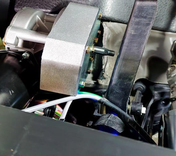
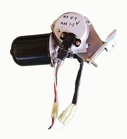
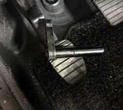
Installation of motor actuator
Before installing the motor actuator, ensure that the clearance between the motor shaft and the clutch pedal is set to 5 mm to prevent interference when the clutch pedal is pressed.
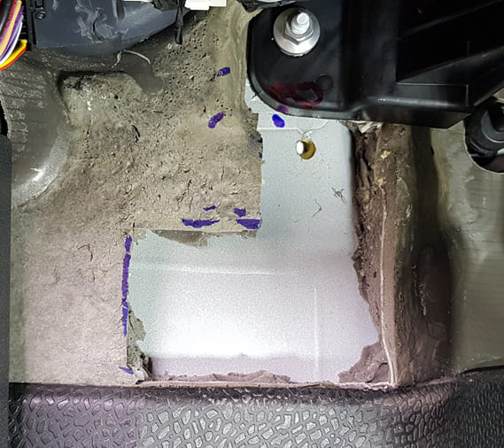
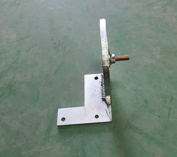
Actuator Bracket Mounting Hole
Cut out the insulation foam as shown and drill an accurate 8 mm bolt hole using the supplied jig.
Use the Supplied Jig
01. Mark and drill the upper 8 mm hole correctly using the supplied jig.
02. Ensure that the actuator is parallel to the clutch pedal, which is tilted approximately 10° to the left.
03. Use 6 mm bolts for the lower two holes.
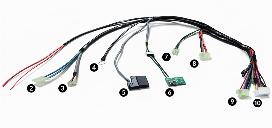
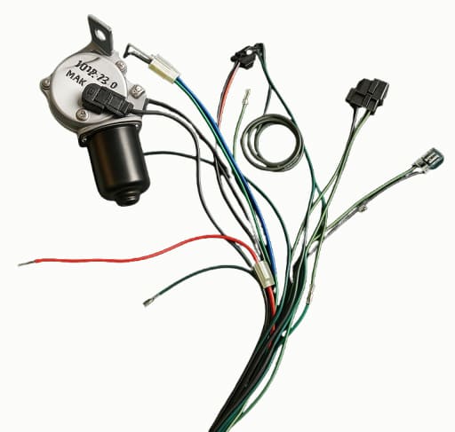
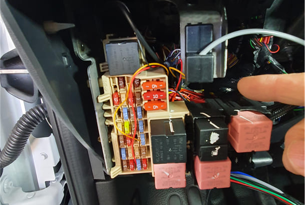
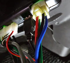
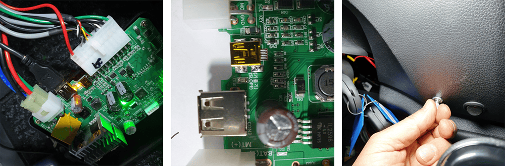
Wiring Harness
The wiring layout is shown from left to right in the photo. Connect the power input to the ignition switch assembly.
2. Blue and green wires: Connect to the motor actuator.
3. Red, black, and white wires: Connect to the motor CPS (Clutch Position Sensor).
4. Black wire: Connect to ground.
5. OBD connector: Connect to the OBD terminal.
6. Slope sensor and encoder: Must be mounted vertically as shown in the photo.
7. 2P green and black wires: Hand knob signal input.
8. 3P black and 2 red wires: Auto/Manual control signal.
9. 4P connector: Main power supply to the motor.
10. Thin red wire: Connect to the Ignition 2 terminal of the ignition switch assembly.
11. 20P connector: Signal input connector.
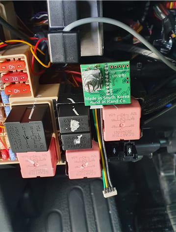
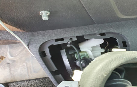
Connection for Each Part
Installation of Slope Sensor and Encoder
Connect the OBD connector to the ECU to transmit digital data.
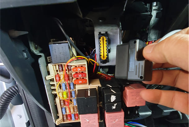
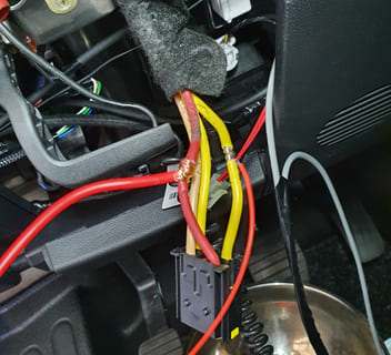
Wiring for main power / IG2 / Ground
Connect the ECU main power (red wire) to the red wire of the ignition switch assembly.
01.
Connect the ECU control power to the yellow wire (IG2) of the ignition switch assembly.
02.
Connect the black ground wire to a chassis bolt.
03.
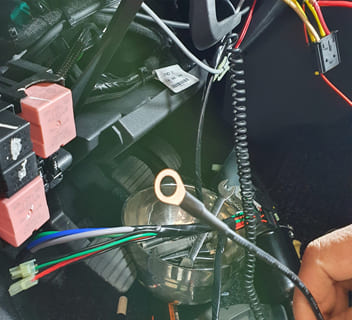
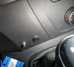
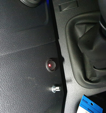
Wiring for main power / IG2 / Ground
Place as shown for auto/manual s.w and Slope sensor/encoder
Ensure that the slope sensor is mounted vertically (90°) as shown in the photo.
01.
Route the wire downward toward the ground.
02.
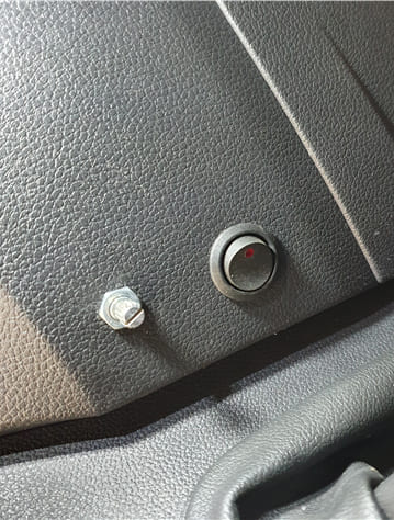
Install the Auto/Manual switch in a 22 mm mounting hole.
03.
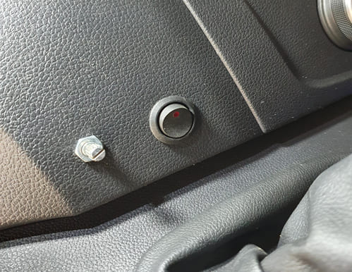
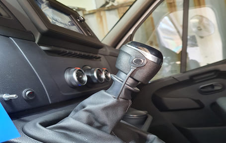
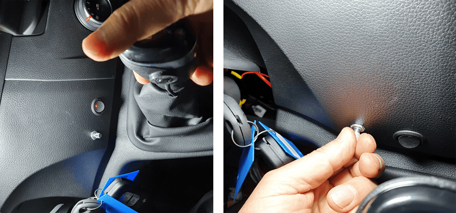
Hand Knob Switch Installation
Secure the wire with a cable tie to prevent damage when the gear is shifted to reverse.
Install the hand knob switch with instant adhesive as shown. Wrap it with insulation tape for 30 minutes to allow it to harden, then remove the tape after it is securely fixed.
01.
Secure the wire with a cable tie to prevent interference when shifting into reverse gear.
02.
Connect the motor and CPS (Clutch Position Sensor) to the ECU.
System Setting
After installing the actuator and wiring, perform the system setup as follows.
1. Start the engine.
2. Turn on the Auto/Manual switch.
3. Connect the scanner to the USB port of the ECU.
4. Turn off the Auto/Manual switch.
5. Install the motor actuator arm on the motor shaft.
6. Press the hand knob switch and check the clearance between the clutch pedal and the bottom of the chassis when the clutch pedal is pressed. Record the CPS value displayed on the scanner.
7. If the clearance is greater than 5 mm, press the VR1 (-) button on the scanner five times briefly. Then press the hand knob switch again and check that the clearance is 5 mm as described above.
Setting Process
Record the CPS value displayed on the scanner. If the clearance is greater than 5 mm:
✔ Press the VR1 (-) button on the scanner 3–5 times briefly.
(The VR1 (-) button on the ECU can also be used.)
✔ Press the hand knob switch again and check that the clearance is adjusted to 5 mm, as described in step 6 above.
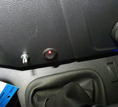
Slope Sensor and Encoder Setup
✔ Place the vehicle on flat ground.
✔ Press the slope sensor/encoder for about 3 seconds. Repeat this 3–5 times until the indicator light on the ECU stays steadily on, as shown.
Clutch Engagement Point Setting
✔ Press the hand knob switch and shift the gear to 1st.
✔ Adjust the slope sensor/encoder so that the display shows 1.0 V higher than the VR1 value
(VR1 value: the value when the clutch pedal is fully pressed while pressing the hand knob switch).
✔ Release the brake pedal and check that the vehicle starts smoothly.
✔ If the start is harsh, turn the encoder counterclockwise until the start becomes smooth.
✔ If the start is slow, turn the encoder clockwise until the vehicle moves smoothly.
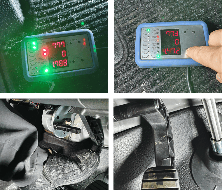
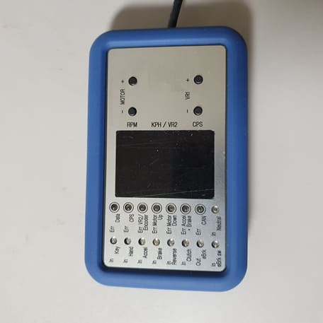
Scanner Check and Test
Scanner
The scanner displays the status of each sensor and related data.
1. RPM : Displays the engine RPM.
2. KPH / VR2 : Displays the vehicle speed when the vehicle is moving.
VR2 : Displays the half-clutch position (voltage value) at which the vehicle starts to move when the brake pedal is released.
3. CPS : Clutch Position Sensor.
4. Motor (+ / −) : Used to test motor operation. The clutch pedal moves up and down when the motor rotates.
5. VR (+ / −) : Used to adjust the fully pressed clutch position.
6. IN : Displays input signals when the related components are activated.
7. ERR : Indicates related system errors.
Road Test
Driving Mode Selection
1. Press the slope sensor/encoder briefly and check for one beep.
This indicates Mode 1, which provides standard starting and is optimized for high-slope conditions.
2. Press it once again to hear two beeps (“beep beep”).
This indicates Middle Start Mode.
3. Press it once more to hear three beeps (“beep beep beep”). This indicates Fast Start Mode.
You can select any mode that suits your driving preference.